Optimization Parameters Nesting
The behavior of the optimization can be influenced by parameter sets. You simply select the parameter set when creating a job.
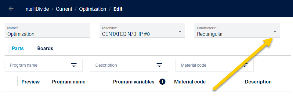
Nesting - Choosing optimization parameter
By default, a Rectangular and a Freeform parameter set are stored, which you can also edit by clicking the pencil icon. You can also create new parameter sets at this point.
Optimization Parameters Nesting
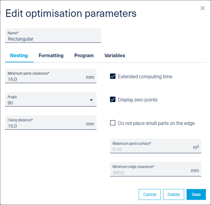
Under the Nesting tab, you can change the Minimum parts clearance and Fixing distance presets.
To improve the quality and quantity of the nesting results Extended computing time can be activated in the optimization parameters. Some customers would like to receive similar nesting plans to reduce the milling marks on the spoilplate on the machine table. This result can be achieved by the extended computing time.
intelliDivide Cutting and Nesting solutions which have been calculated using the option extended computing time are getting highlighted in the solution overview on the left side.
Note: Only available for intelliDivide Nesting Advanced and intelliDivide Cutting Premium.
The rotation angle can be varied between 0 degrees, 90 degrees and Free. If you only want to produce right-angled pieces, it is recommended to leave the rotation angle at 90 degrees.
Show zero points causes the workpiece coordinate system to be displayed at the zero point for each workpiece in the nesting pattern. This enables you to see immediately how the workpiece was rotated in the plan.
In the nesting process, the raw board is usually clamped via vacuum on a so-called spoilboard (usually MDF). This board can be milled into. It is milled over after a certain number of cycles and is thus flat again. The vacuum is at its lowest at the edge of the spoilplate, since foreign air is sucked in here through the open edges. With the setting Do not place small parts on the edge, you can avoid this effect and move the parts from the edge towards the center of the plate when they reach a certain size. For this purpose, it is necessary to define the maximum part area and the minimum edge distance.
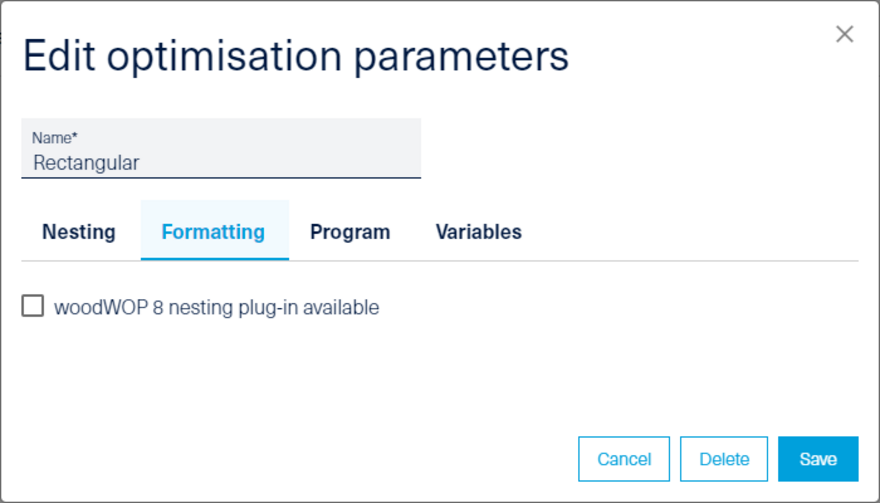
Optimization parameters - formatting disabled
Via the Formatting tab, nesting additional functions can be used. When calculating the nesting plans, a new, additional woodWOP macro is generated in the nesting plan - the "Format" macro.
NOTE: These functions are only available in connection with woodWOP 8 and the woodWOP Nesting Plugin.
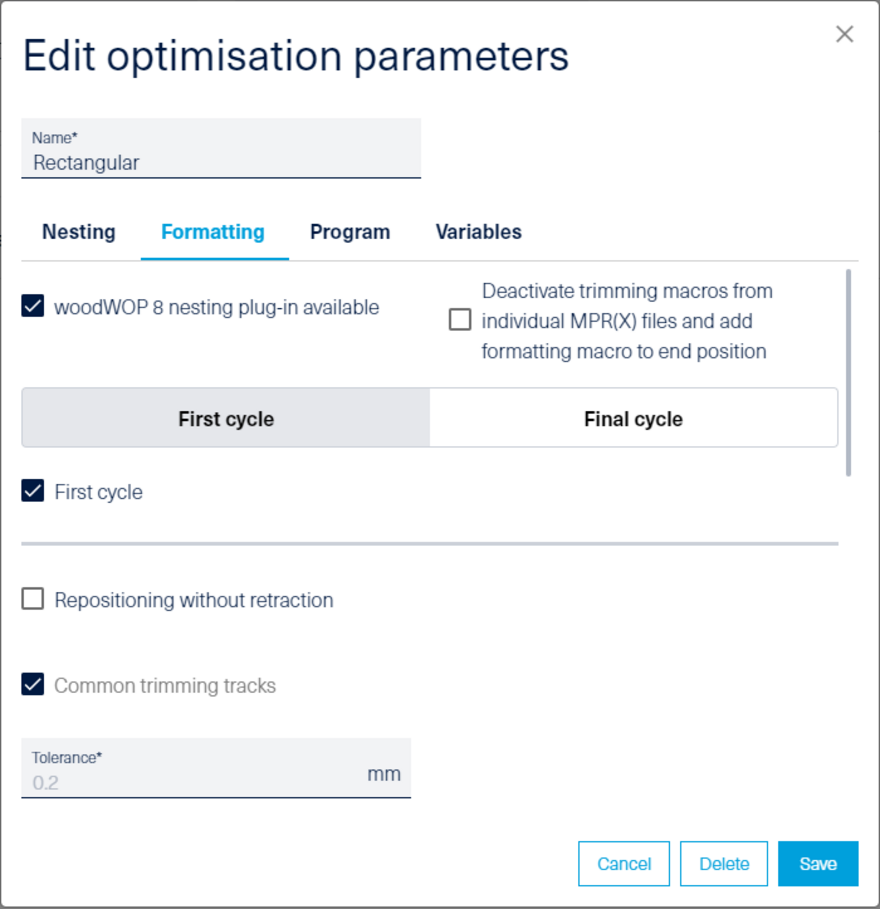
Optimization parameters - formatting enabled
The following processing strategies can be achieved by formatting:
- Repositioning without retraction (stay down)
- Use common milling tracks (common line)
- Include tabs / NOTE: available as of woodWOP 8.1.225
- Milling in steps (onion skinning)
By activating "First pass" and "Final pass", up to two successive formatting macros can be added. All nesting contours present in the single MPR files are used for the toolpath calculation.
Normally, the single MPR files already contain milling macros for formatting. If these are to be ignored and only the new, added formatting macro is to be used, the checkbox "Deactivate trimming macros from individual MPR(X) files and add formatting macro to end position" must be selected.
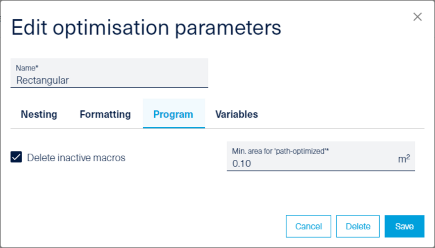
Optimization parameters - program
Delete inactive macros causes woodWOP macros that are invalid due to conditions in the nesting result to be removed. This makes the newly created nest with the woodWOP edits clearer. Only what actually needs to be processed is displayed in the woodWOP result.
An important factor influencing the safe clamping of a workpiece during nesting is its surface area. The smaller the workpieces, the more likely they are to slip on the spoilplate.
Since the vacuum is greatest at the beginning of machining the nest, small workpieces should be machined first. With the parameter Minimum area for path optimized, the workpieces are processed in the order from small to large until this limit value is reached.
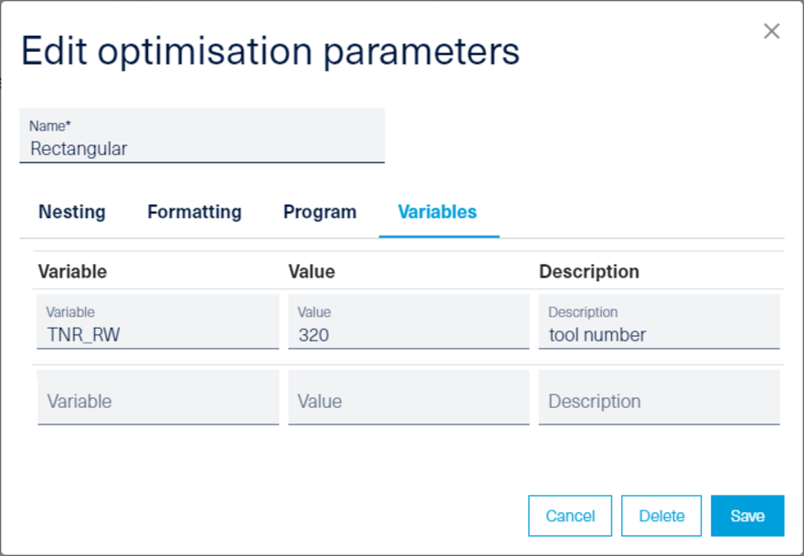
Optimization parameters - variables
In the Variables area, variable names and values can be entered that are used in the workpieces to be nested. This allows you to specify during optimization, for example, with which current tool numbers the nest should be created. If, for example, a certain tool number is not available on the machine at the moment, you can overwrite all tool numbers from the individual MPR files in this way. All variables entered here are not automatically numbered.