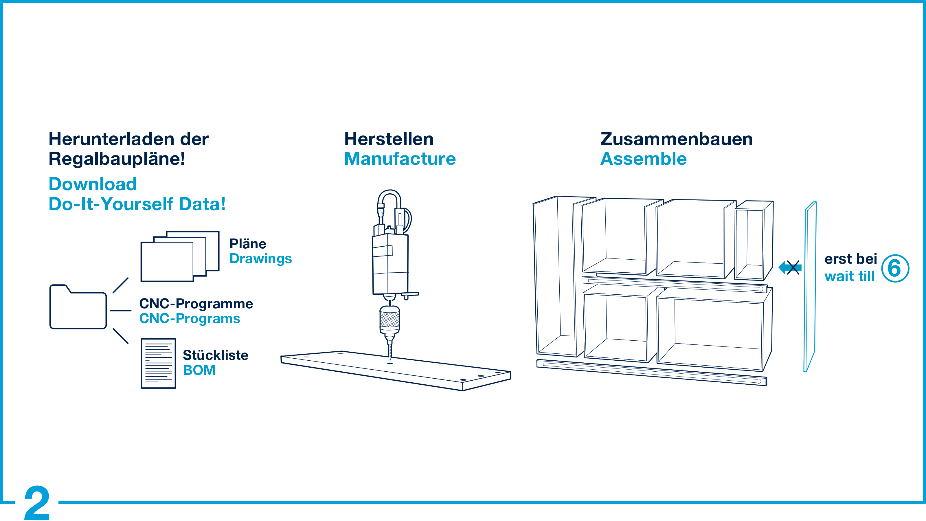
Construction plans
Construction plans for the sorting rack
The components of our "Sorting Production Set" also include construction plans for the "productionRack Sorting" sorting rack, which we provide you with.
You can download all related data under the download link on the right side (Download construction plans).
Under the download links you will find a package with the following data:
- Dawings sorting rack
- Cutting list (Excel format)
- Fittings and material list
- CNC programs (MPR format)
- Nesting CNC programs (MPR format) for nesting process
Please note that the construction plans are designed for a panel thickness of 19 mm.
If you want to integrate the components into an existing solution, take a look at the mounting dimensions.

Get your Hardware!
Build your rack
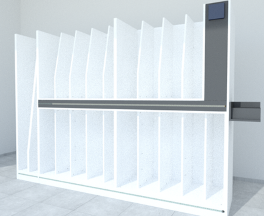
Example picture productionRack Sorting Sorting rack
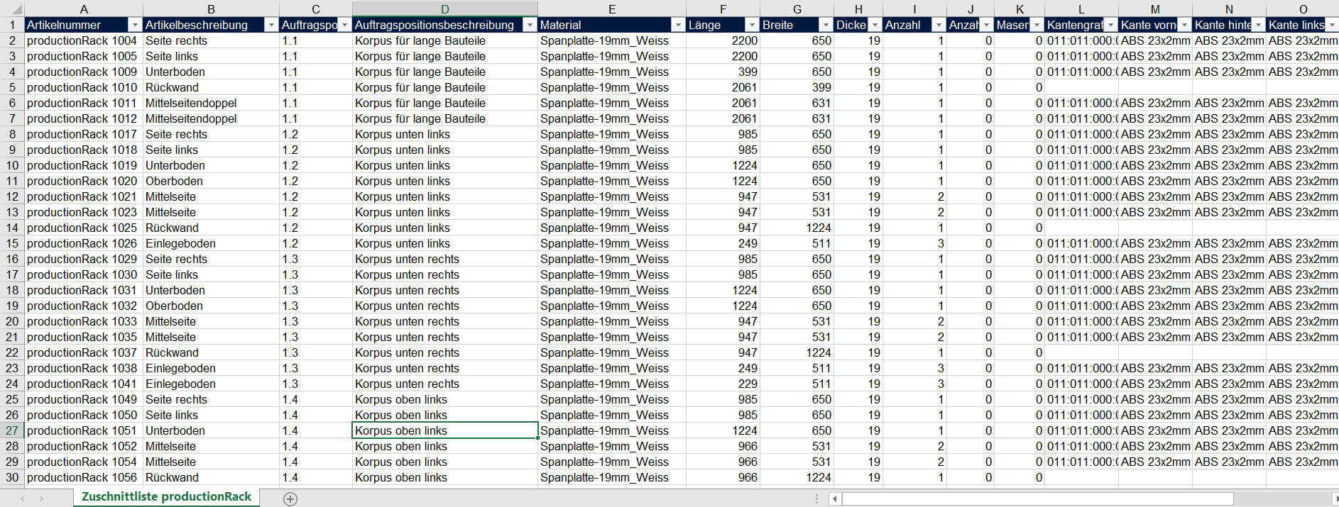
Cutting list productionRack Sorting Sorting rack
Drawing set for the sorting rack
This PDF drawing set contains dimensioned drawings of the individual carcases and parts for assembly.
You can assign the individual carcasses to the drawings using the columns "Order line" and "Order line description" in the cutting list.
The drawing set contains the following overview and detail drawings:
Drawing number | Drawing name |
1.0 | Overview drawing sorting rack |
1.1 | Carcase for long parts |
1.1 | Carcase for long parts middle panels |
1.2 | Carcase bottom left |
1.3 | Carcase bottom right |
1.4 | Carcase top left |
1.5 | Carcase top right |
1.5 | Carcase for electrical components |
1.6 | Carcase for electrical components shelves |
2.0 | Side panel double and covers |
2.1 | Cover lower LED bar |
2.1 | Cover lower LED bar solid wood |
2.1 | Cover lower LED bar left part |
2.2 | Cover middle LED bar |
2.3 | Cover middle LED bar solid wood |
2.4 | Side panel doubles |
3.0 | Tablet mount |
3.1 | Tablet mount details |
Cutting list for the sorting rack
The cutting list contains all the parts you need to build the sorting rack. You can easily import this list into a cutting optimization software (e.g. intelliDivide Cutting or Schnitt Profi(t)). The types of panel materials required for cut optimization can be found in the material and fittings list.
Carcasses
The edgeband rack consists of 6 carcasses, which are assembled individually. The lower carcasses stand on the floor with base adjustable feet. The upper carcasses are mounted on an intermediate layer of solid wood slats for stability. Finally, you can close the gaps with covers and visible sides.
All required carcass components are grouped together in order lines 1.0 - 1.6.
4 carcasses (2 each for the lower half and 2 for the upper half) are used to store the smaller and medium-sized parts.
In addition there are 2 more narrow carcasses. The right carcass is used to hold the electronics, the left carcass as a compartment for long components.
Side panel doubles and covers
In order lines 2.0 - 2.4 we have summarised all the required side panel doubles and covers.
The side panel doubles are mounted at the end. They form the left and right end of the sorting rack.
The grooves for the LED strips are milled into the front covers.
The rear panels serve as spacers. The covers are screwed to a 40 mm solid wood strip at the front and back.
Tablet mount
Order lines 3.0 - 3.1 includes all parts required for the tablet mount. This mount is optional. However, we recommend the use of this proven tablet mount because it has a decisive advantage: You can easily build it yourself!
Alternatively, you can also use a commercially available tablet mount.
Cutting list details
The article number in the cutting list serves as a unique identifier for each part.
The cut list contains various additional part information such as edge information and the CNC program names (*.mpr). If two CNC programs are required to machine a part, the name of the second CNC program is given in the column "CNC program 2".
Fittings and material list for the sorting rack
The fittings and material list gives you an overview of the required quantity of edgeband and panel materials and the type and number of fittings required.
For the construction we have used the most common excenter connectors, dowels and hinges.
If possible, the fittings should correspond to the planned, required drilling pattern.
Alternatively, you can of course adapt the drilling patterns in the CNC programs if you wish to use other fittings.
The required fittings such as excenter connectors, dowels and hinges can be obtained from various suppliers.
The required drill holes for the listed fittings are already programmed in the CNC programs provided.
CNC programs for the sorting rack
This CNC program set in MPR format contains the CNC programs required for the individual parts for CNC machining.
You can assign the corresponding MPR programs to the parts using the columns "CNC program 1" and "CNC program 2" in the cutting list.
If two CNC programs are required for machining one part, you will find the name of the second CNC program in the column "CNC program 2".
Details: Excenter of the excenter connection
If you want to glue your rack instead of using excenter connectors, you can set the "Fix" variable from "1" to "0" in the CNC program. This deactivates all holes for excenter housings and bolts.
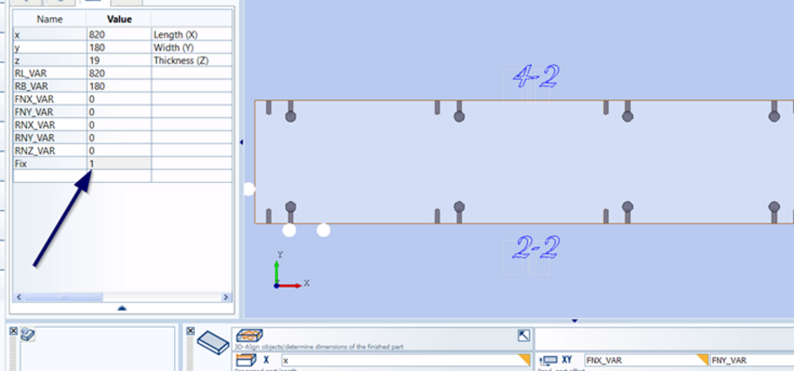
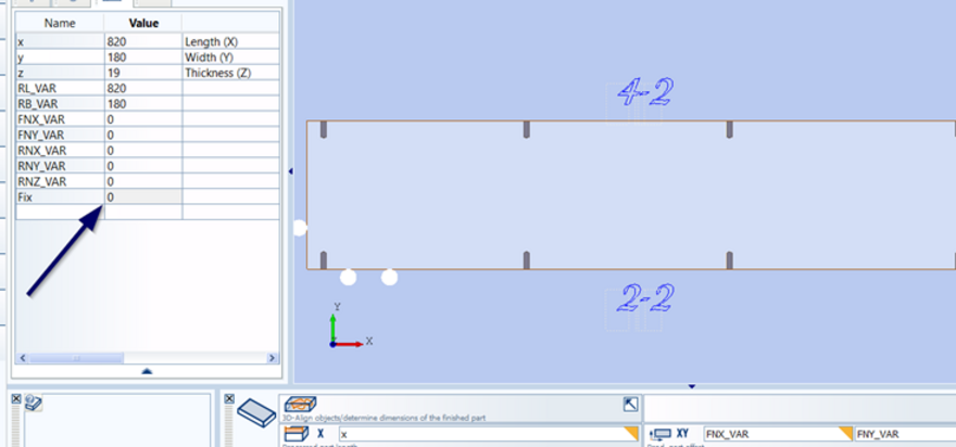
Enabled excenter connection drillings
Disabled excenter connection drillings
Details: Global variables
Create a global variable list (wwglob.var) using your woodWOP software and assign your own tool numbers..
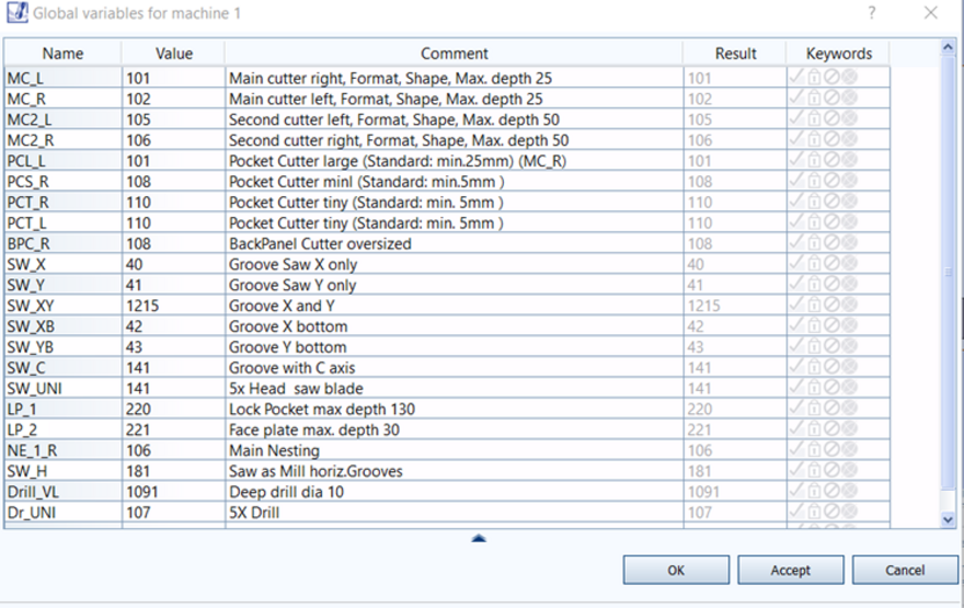
Global variable table wwglob.var
Nesting CNC programs for the sorting rack
The zip folder "Nesting CNC programs productionRack Sorting 19mm" contains all the information you need for nesting:
- Nesting CNC program set in MPR format
- Cutting list for nesting
- Further CNC programs required, in MPR format, which contain machining operations that cannot be processed using nesting.
You can assign the corresponding MPR programs to the parts using the columns "CNC program 1" and "CNC program 2" in the cutting list.
If two CNC programs are required for machining one part, you will find the name of the second CNC program in the column "CNC program 2".
The corresponding CNC programs for the second machining operation can be found in the folder "CNC Program 2" in the Zip folder.
Please note that you must use the cutting list also available in this folder for nesting.
Terms of use of the construction plans
The construction plans were drawn up to the best of our knowledge and with due regard to professional concerns.
Despite careful checking, errors may occur in combination with your machine and software settings, for which HOMAG cannot accept any liability.
In addition, the installation situation, load, anchoring and stability of the racking must be individually checked and ensured.
By downloading the construction plans, the customer agrees to check the construction plans for possible errors and is responsible for the use of the construction plans and the CNC programs and the resulting racking.